FreeCore Function #10:
Numerically
Controlled Oscillator/Modulator
Module name:
nco
Current release: version 1.0, August 20,
1997
Contributed by: Rune Baeverrud
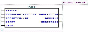
Shown below is the schematic representation of the NCO:

This is a very high speed Numerically Controlled Oscillator/Modulator achieving an operating speed of more than 80MHz input clock frequency using an Altera FLEX 10K -3 device. The NCO Module makes extensive use of pipelining to achieve this high speed.
The NCO Module provides very high frequency resolution, using a 25-bit phase accumulator/register, and a 20-bit frequency control word. The inclusion of a phase offset input let you modify the phase at any time, making the NCO Module ideal for phase modulation as well as high-precision frequency modulation.
I have also provided a Start and Stop input, which enables and disables the NCO Module Wave[] output as close as possible to the waveform zero crossings. This causes minimum noise operation when enabling or disabling the waveform output.
The NCO operates continuously. The Start and Stop inputs only enables or disables the actual output of the Module, normally causing a slight delay waiting for a waveform zero crossing.
At every clock cycle, the 20-bit Frequency[19..0] input is added to the internal 25-bit phase accumulator register. The nine most significant bits of the phase accumulator (bits [24..16]) is fed to a 512-point sine lookup-table provided by the Sine Module also available in the FreeCore Library.
The frequency span is huge, with a frequency step resolution of fSysClk / (2^25). The actual sine frequency output is given as fout = fSysClk * (Frequency[19..0])dec / (2^25).
| PARAMETERS | |
| POLARITY | Set to "UNIPOLAR" (2..128..254) operation or "BIPOLAR" (-126..0..126) operation (using 2's complement). |
| INPUT PORTS | |
| SysClk | System clock input. More than 80MHz is possible using a FLEX 10K -3 device. |
| Frequency[19..0] | Frequency control input, causing the Wave[] output frequency to be fout = fSysClk * (Frequency[19..0])dec / (2^25) as described above. |
| Offset[8..0] | Phase offset input. This input is added to the Angle value provided as input to the Sine Module, making a phase offset in the range -180 deg..180 deg possible. Remember that because of the extensive use of pipelining, there is a 5 SysClk delay before the Offset[] input is visible at the output. |
| Start | When set to high for a short moment (it is sampled on every SysClk rising edge), then the NCO output will be enabled at the next NCO wave output zero crossing. |
| Stop | When set to high for a short moment (it is sampled on every SysClk rising edge), then the NCO output will be disabled at the next NCO wave output zero crossing. |
| OUTPUT PORTS | |
| Wave[7..0] | Digital Waveform output, unipolar or bipolar, depending on the POLARITY parameter setting. |
| Running | A logic high on this output signals that the NCO output is enabled. |
| ZeroCross | This output goes high for one SysClk period at every zero crossing on the NCO wave output. Used internally for enabling and disabling of the wave output, and could be used externally for counting Sine cycles. ZeroCross is also active when the wave output is disabled. |
NOTE: You need to copy the files COS180N.MIF and COS180P.MIF to your current working directory.
Enjoy!
![]()
Last updated 08 Feb 2001 11:53